 Download:
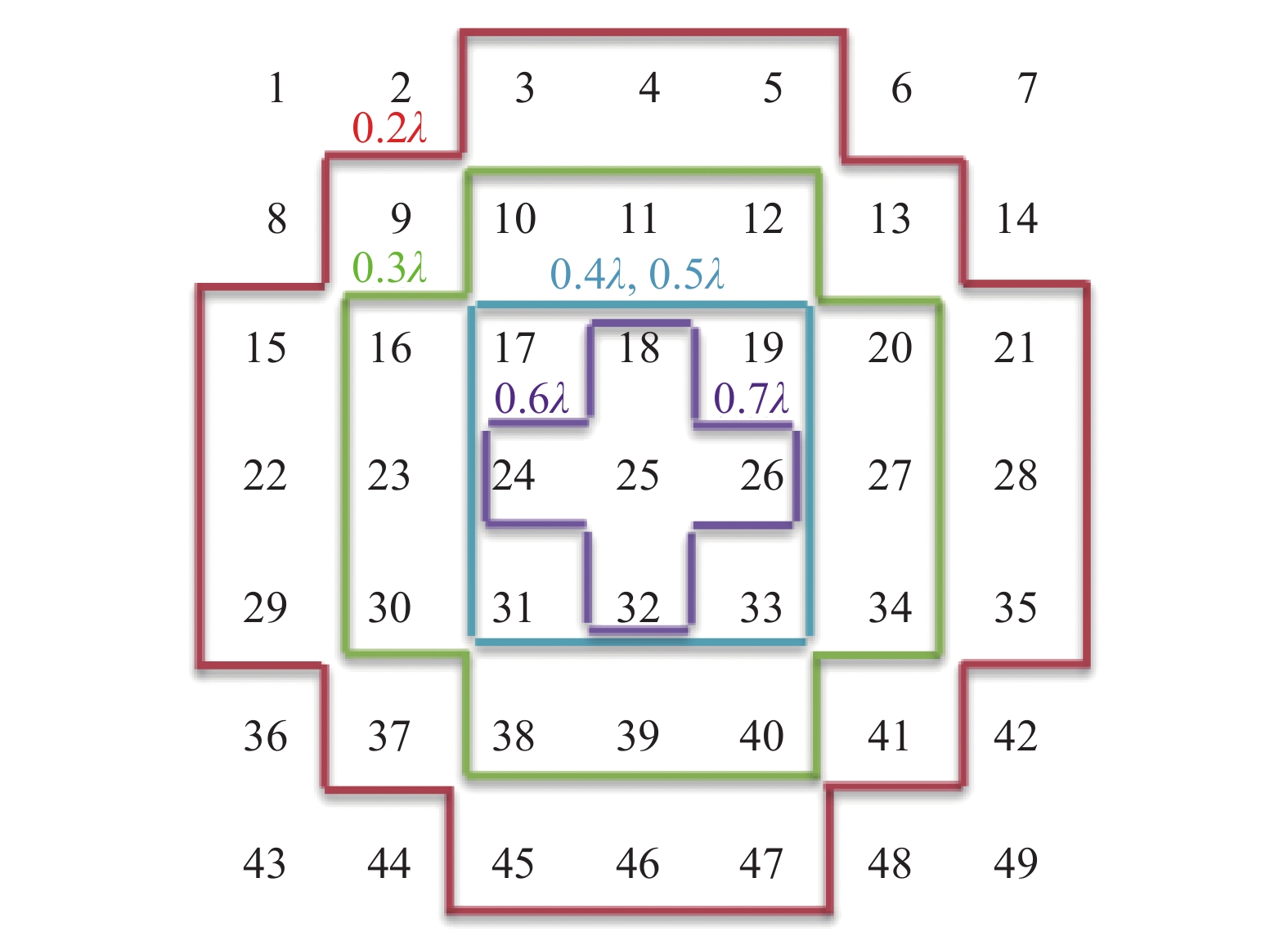
Element arrangement and corresponding −10 dB edge taper area of the focal field at different spacings.
Figures of the Article
-
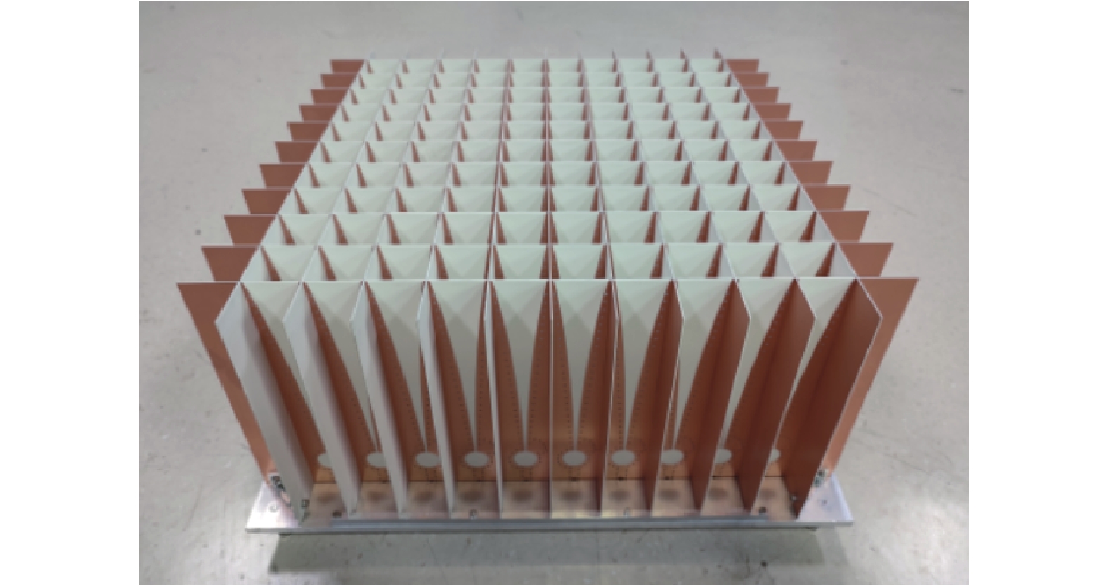
![]() Photograph of the Vivaldi PAF array.
Photograph of the Vivaldi PAF array.
-
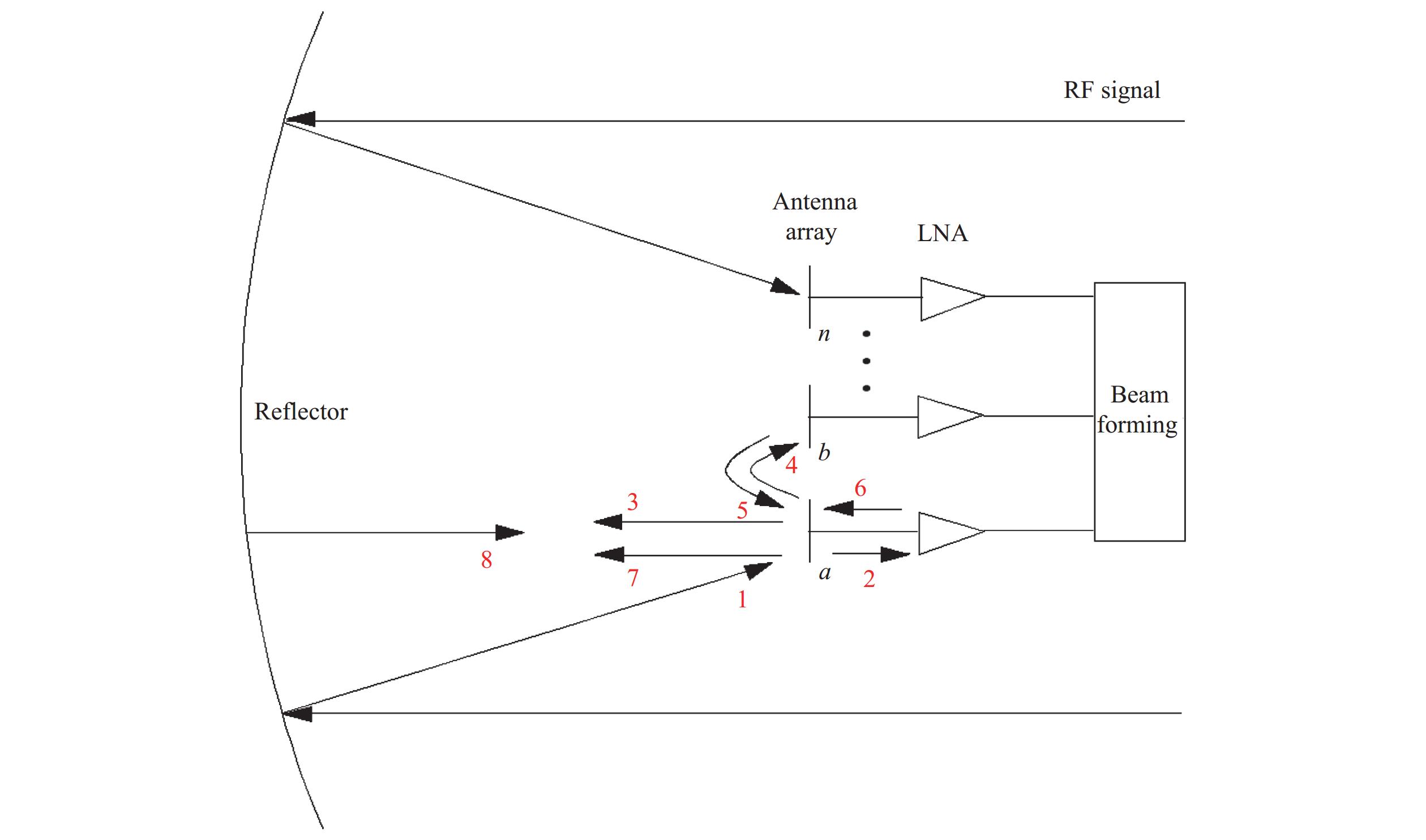
![]() Coupling path of a PAF. Red numbers represent different types of signals throughout the transmission path, while LNA refers to low noise amplifiers.
Coupling path of a PAF. Red numbers represent different types of signals throughout the transmission path, while LNA refers to low noise amplifiers.
-
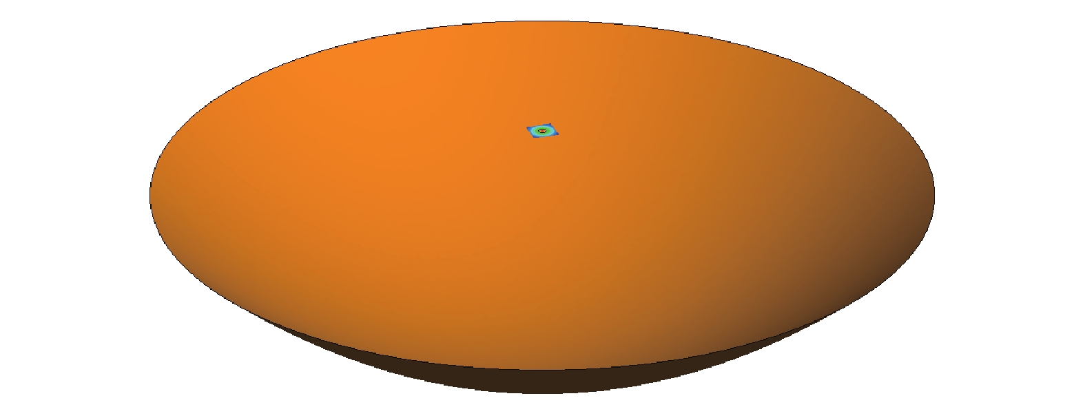
![]() 25 m reflector and focal field distribution.
25 m reflector and focal field distribution.
-
![]() Element arrangement and corresponding −10 dB edge taper area of the focal field at different spacings.
Element arrangement and corresponding −10 dB edge taper area of the focal field at different spacings.
-
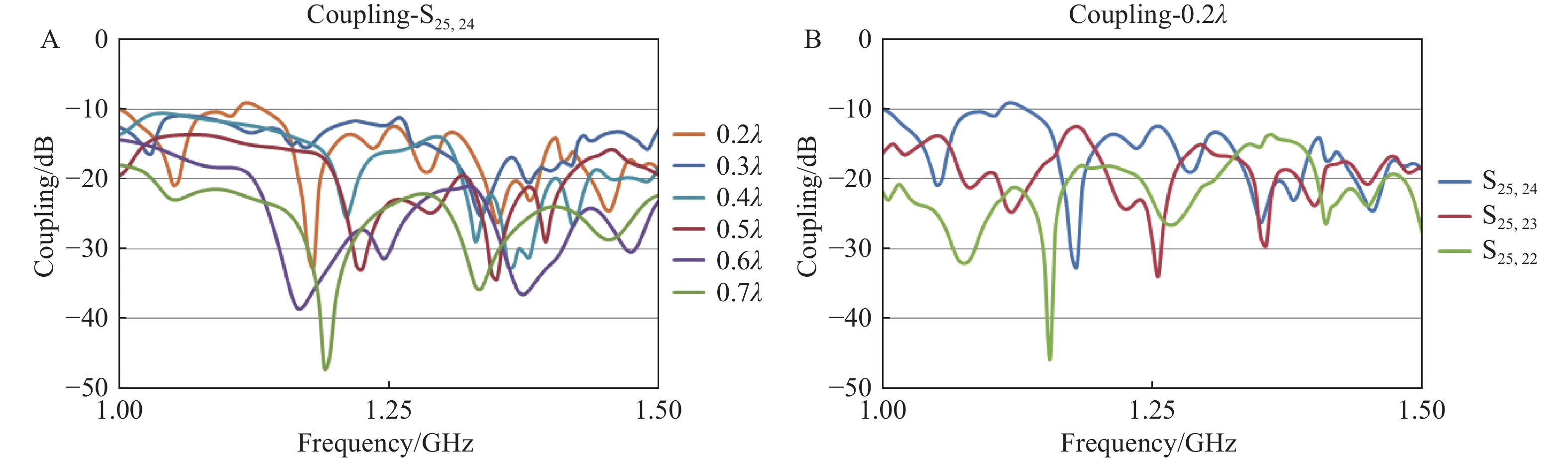
![]() Simulation results of coupling between elements 25 and 24 at different spacing, as well as elements 24, 23, and 22 at 0.2λ spacing.
Simulation results of coupling between elements 25 and 24 at different spacing, as well as elements 24, 23, and 22 at 0.2λ spacing.
-
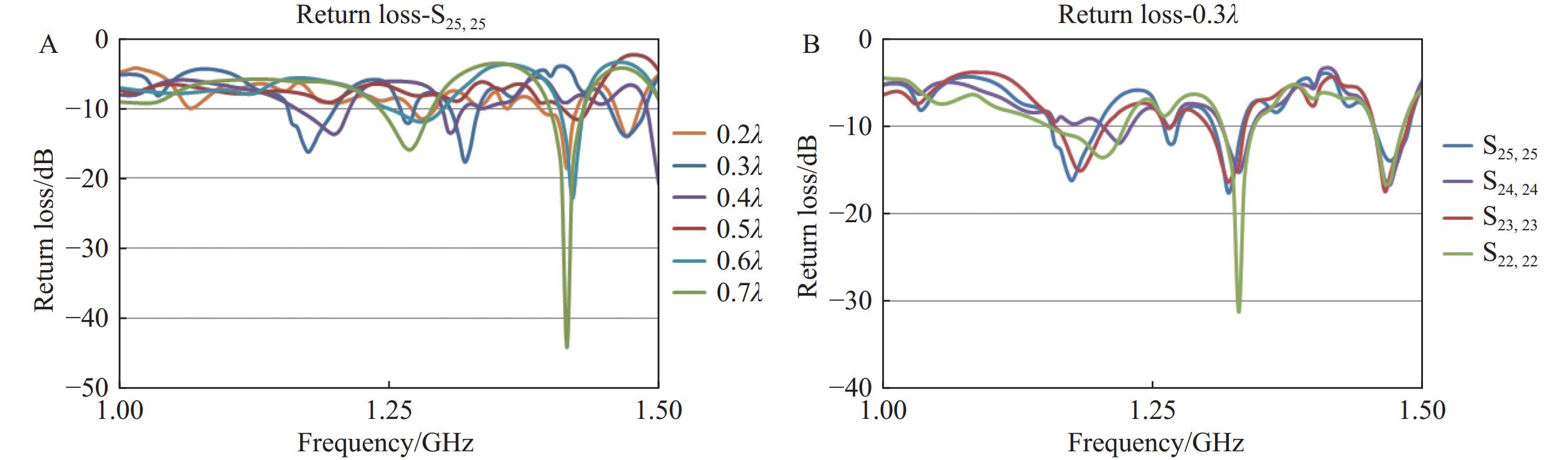
![]() Simulation results of return loss for element 25 at different spacings, as well as elements 22, 23, 24, and 25 at 0.3λ spacings.
Simulation results of return loss for element 25 at different spacings, as well as elements 22, 23, 24, and 25 at 0.3λ spacings.
-
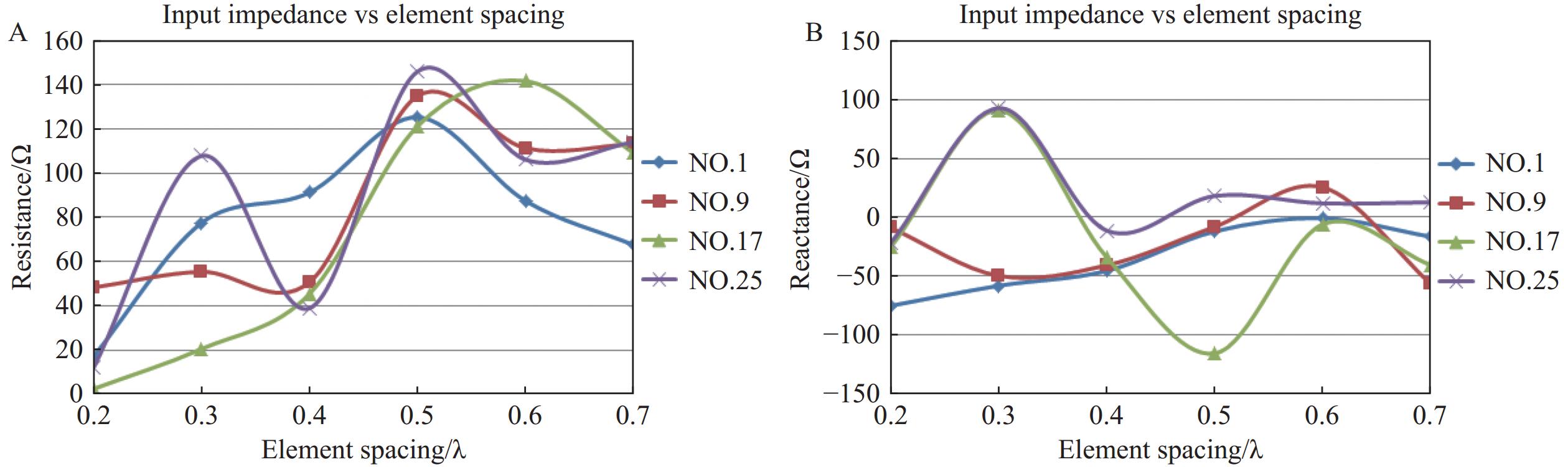
![]() Simulation results of input impedance with resistance and reactance for elements 1, 9, 17, and 25 at different spacings.
Simulation results of input impedance with resistance and reactance for elements 1, 9, 17, and 25 at different spacings.
-
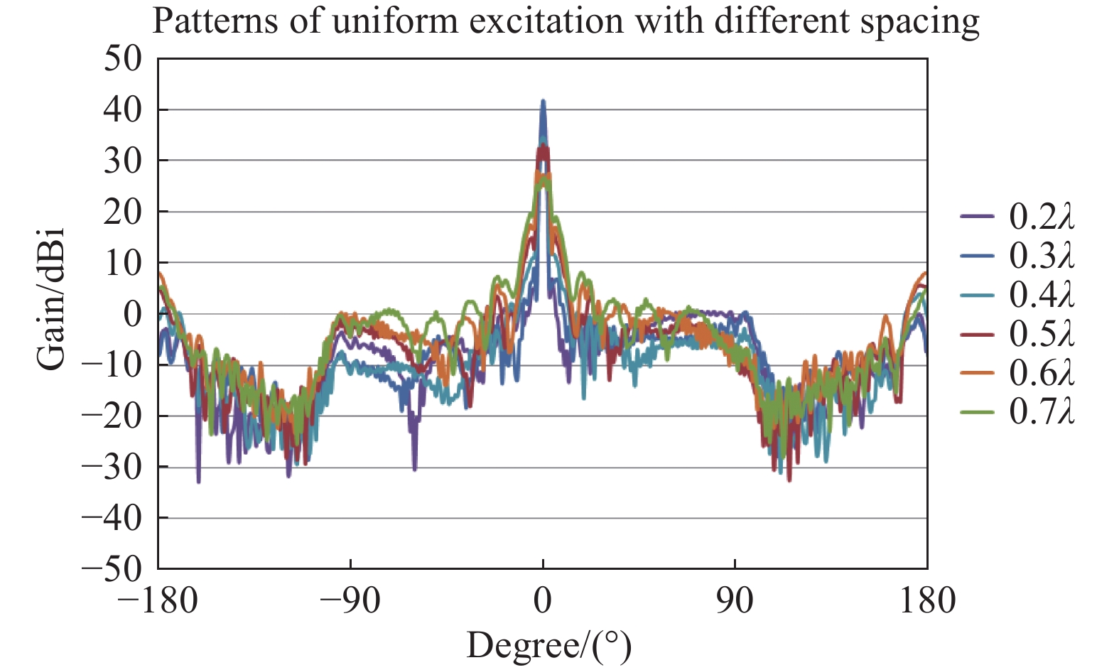
![]() Simulation results of beamforming patterns using PAFs combined with reflectors, under uniform excitation across the entire array, at different spacings.
Simulation results of beamforming patterns using PAFs combined with reflectors, under uniform excitation across the entire array, at different spacings.
-
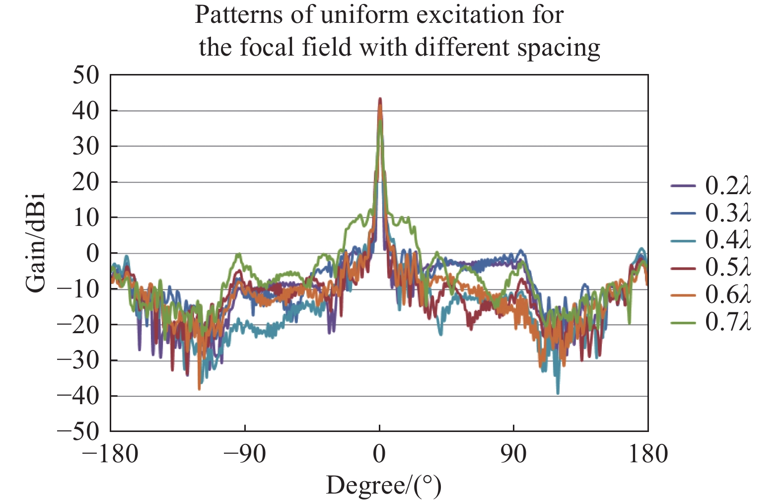
![]() Simulation results of beamforming patterns using PAFs combined with reflectors, under uniform excitation by the focal field, at different spacings.
Simulation results of beamforming patterns using PAFs combined with reflectors, under uniform excitation by the focal field, at different spacings.
-
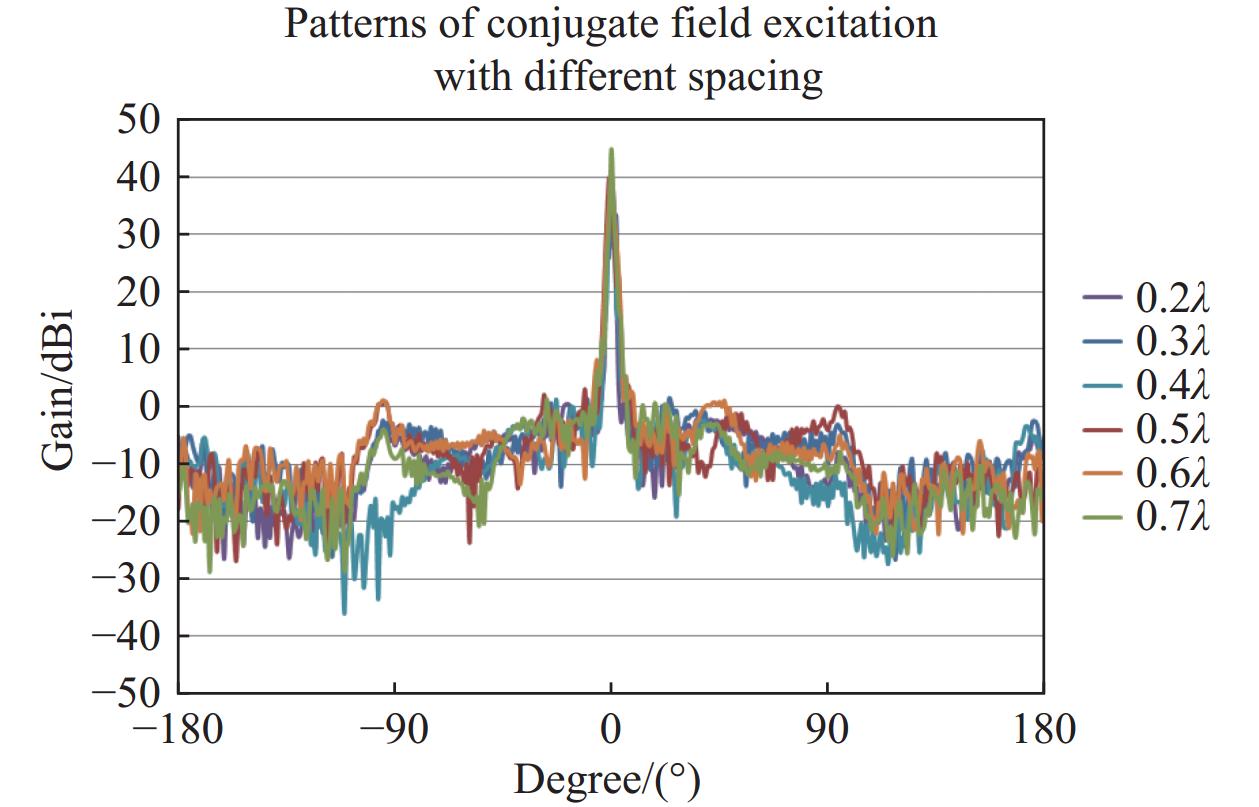
![]() Simulation results of beamforming patterns using PAFs combined with reflectors, under conjugate field matching excitation by the focal field, at different spacings.
Simulation results of beamforming patterns using PAFs combined with reflectors, under conjugate field matching excitation by the focal field, at different spacings.
-
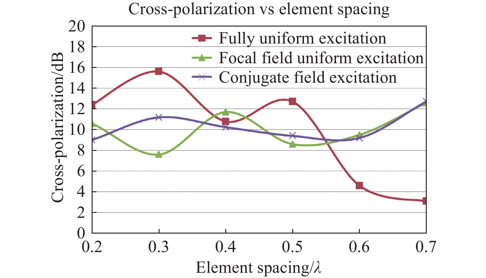
![]() Simulation results of cross-polarization using PAFs combined with reflectors, with different excitation spacings.
Simulation results of cross-polarization using PAFs combined with reflectors, with different excitation spacings.
-
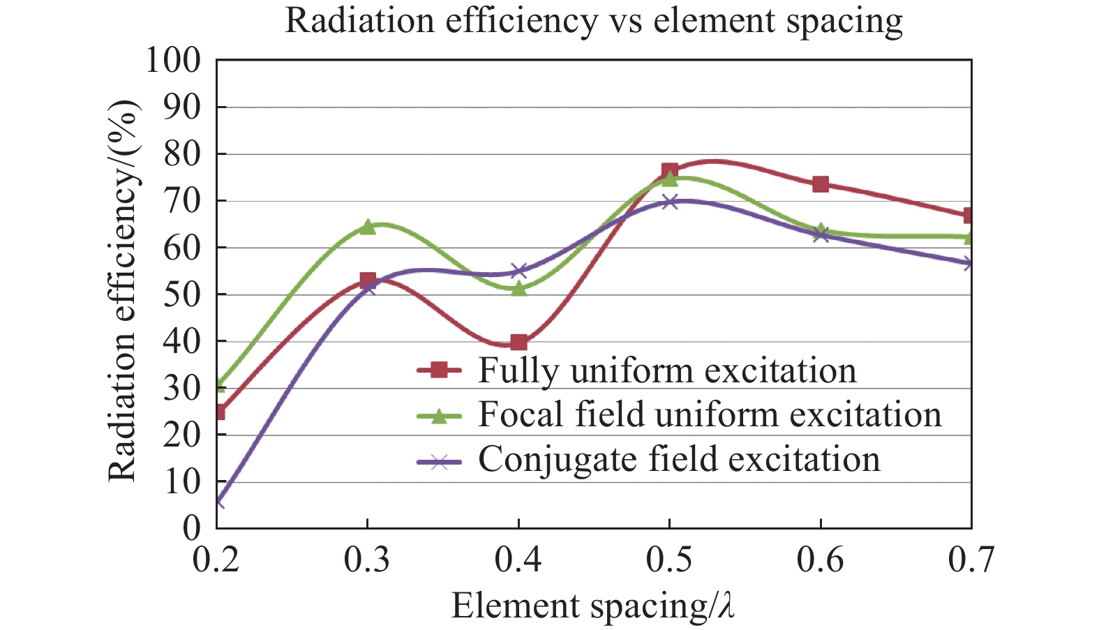
![]() Simulation results of radiation efficiency using PAFs combined with reflectors under different excitation and spacings.
Simulation results of radiation efficiency using PAFs combined with reflectors under different excitation and spacings.