 Download:
Effects of the loss tangent on beam pattern.
Figures of the Article
-
![]() Several designs of membrane antennas.
Several designs of membrane antennas.
-
![]() |S11| of the dipole membrane antenna.
|S11| of the dipole membrane antenna.
-
![]() The beam patterns of the dipole model on the E-plane (A) and H-plane (B), simulated in free space.
The beam patterns of the dipole model on the E-plane (A) and H-plane (B), simulated in free space.
-
![]() The beam patterns of the dipole model on the E-plane (A) and H-plane (B), simulated on a modeled lunar surface.
The beam patterns of the dipole model on the E-plane (A) and H-plane (B), simulated on a modeled lunar surface.
-
![]() Geometric structure of the membrane antenna.
Geometric structure of the membrane antenna.
-
![]() Aerial photograph of a membrane prototype antenna, taken by a drone.
Aerial photograph of a membrane prototype antenna, taken by a drone.
-
![]() Optimization of membrane antenna parameters.
Optimization of membrane antenna parameters.
-
![]() Illustration of the impedance-transforming balun, showing physical dimensions, and a photograph of the balun used.
Illustration of the impedance-transforming balun, showing physical dimensions, and a photograph of the balun used.
-
![]() S-parameter measurement of the balun. The red and blue lines represent |S11| and |S21|, respectively.
S-parameter measurement of the balun. The red and blue lines represent |S11| and |S21|, respectively.
-
![]() The measured |S11| on the ground.
The measured |S11| on the ground.
-
![]() The relative permittivity (A) and loss tangent (B) of lunar soil as a function of density.
The relative permittivity (A) and loss tangent (B) of lunar soil as a function of density.
-
![]() Schematic diagram showing a simplified lunar surface structure model, with relative permittivities and loss tangents.
Schematic diagram showing a simplified lunar surface structure model, with relative permittivities and loss tangents.
-
![]() Simulation results for a membrane antenna in free space.
Simulation results for a membrane antenna in free space.
-
![]() (A) Antenna impedance on the lunar surface. (B) |S11| for various reference impedance values.
(A) Antenna impedance on the lunar surface. (B) |S11| for various reference impedance values.
-
![]() Comparison of |S11| for different relative permittivity (A) and loss tangent (B).
Comparison of |S11| for different relative permittivity (A) and loss tangent (B).
-
![]() The beam pattern of the membrane antenna model.
The beam pattern of the membrane antenna model.
-
![]() Effects of relative permittivity on beam pattern .
Effects of relative permittivity on beam pattern .
-
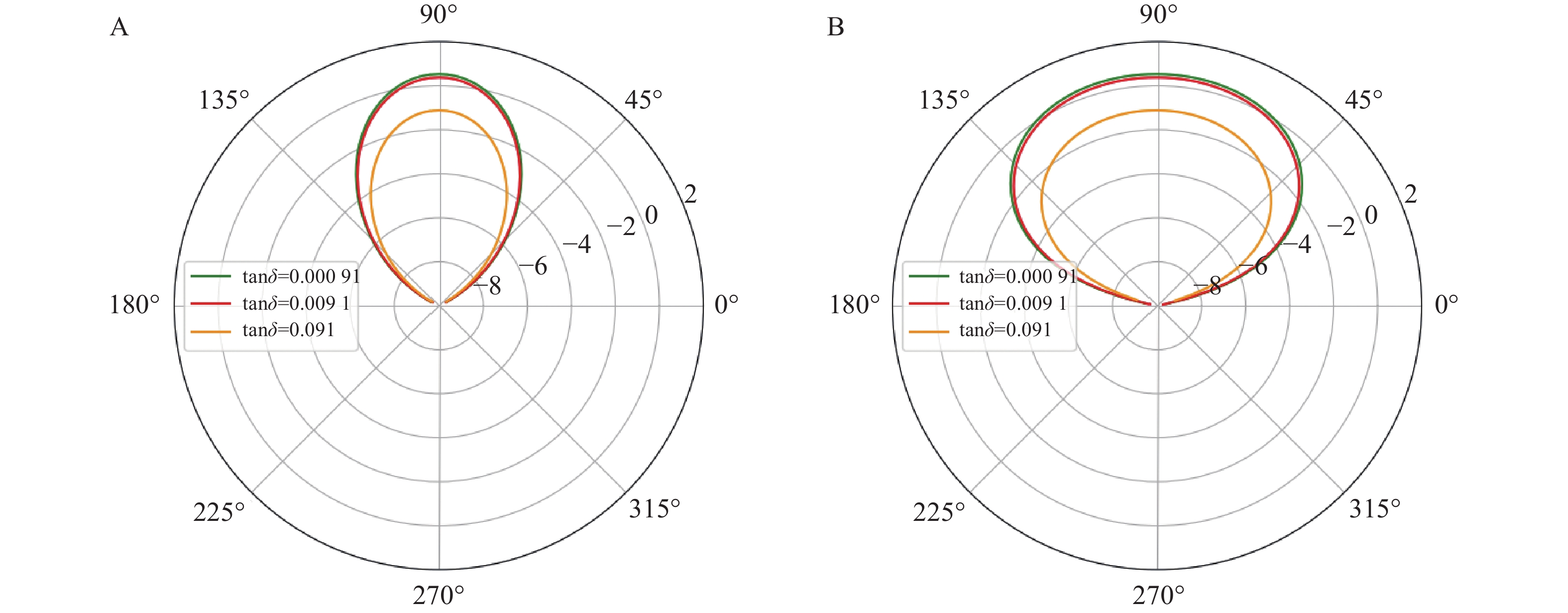
![]() Effects of the loss tangent on beam pattern.
Effects of the loss tangent on beam pattern.
-
![]() Comparison of antenna efficiency of membrane antennas in free space and on the lunar surface.
Comparison of antenna efficiency of membrane antennas in free space and on the lunar surface.


Related articles
-
2023, 20(3): 211-218. DOI: 10.14005/j.cnki.issn1672-7673.20230314.004
-
2022, 19(6): 552-558. DOI: 10.14005/j.cnki.issn1672-7673.20220601.001
-
2022, 19(2): 179-188. DOI: 10.14005/j.cnki.issn1672-7673.20210415.004
-
2021, 18(4): 472-476. DOI: 10.14005/j.cnki.issn1672-7673.20210429.002
-
2016, 13(2): 170-177.
-
2013, 10(1): 99-102.
-
1999, 0(S1): 254-258.
-
1999, 0(S1): 249-253.
-
1999, 0(S1): 90-93.
-
1999, 0(S1): 51-52.